I seem to remember yanking one out of the body cavity above/behind the ecu.... but I don't remember the size/colour/shape, just that one was a pita to get out
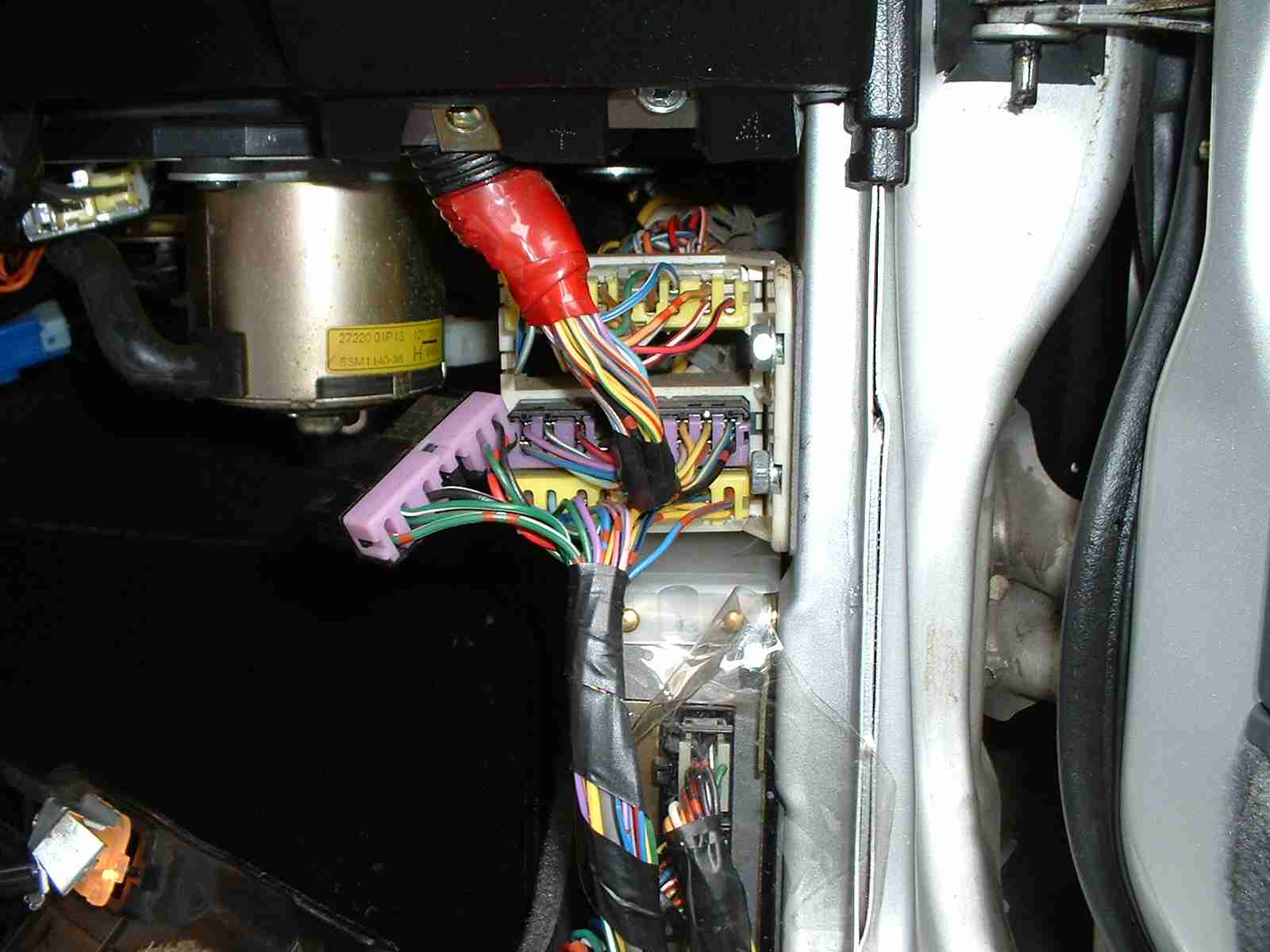
I'm going to try the red/white wire.
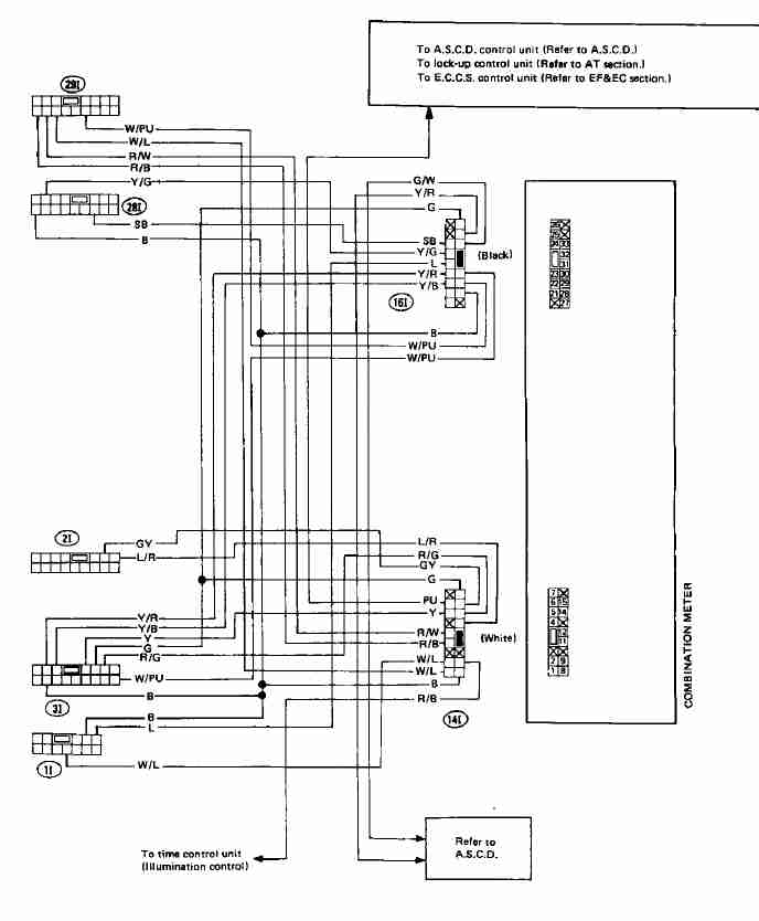
This wire is suppose to pulse 5 volts, 24 times per revolution. The output from the digi to ecu Pin 29 is 5 volts 2 pulses per revolution.
Anybody know MPH to speed sensor revolutions ecu or otherwise?
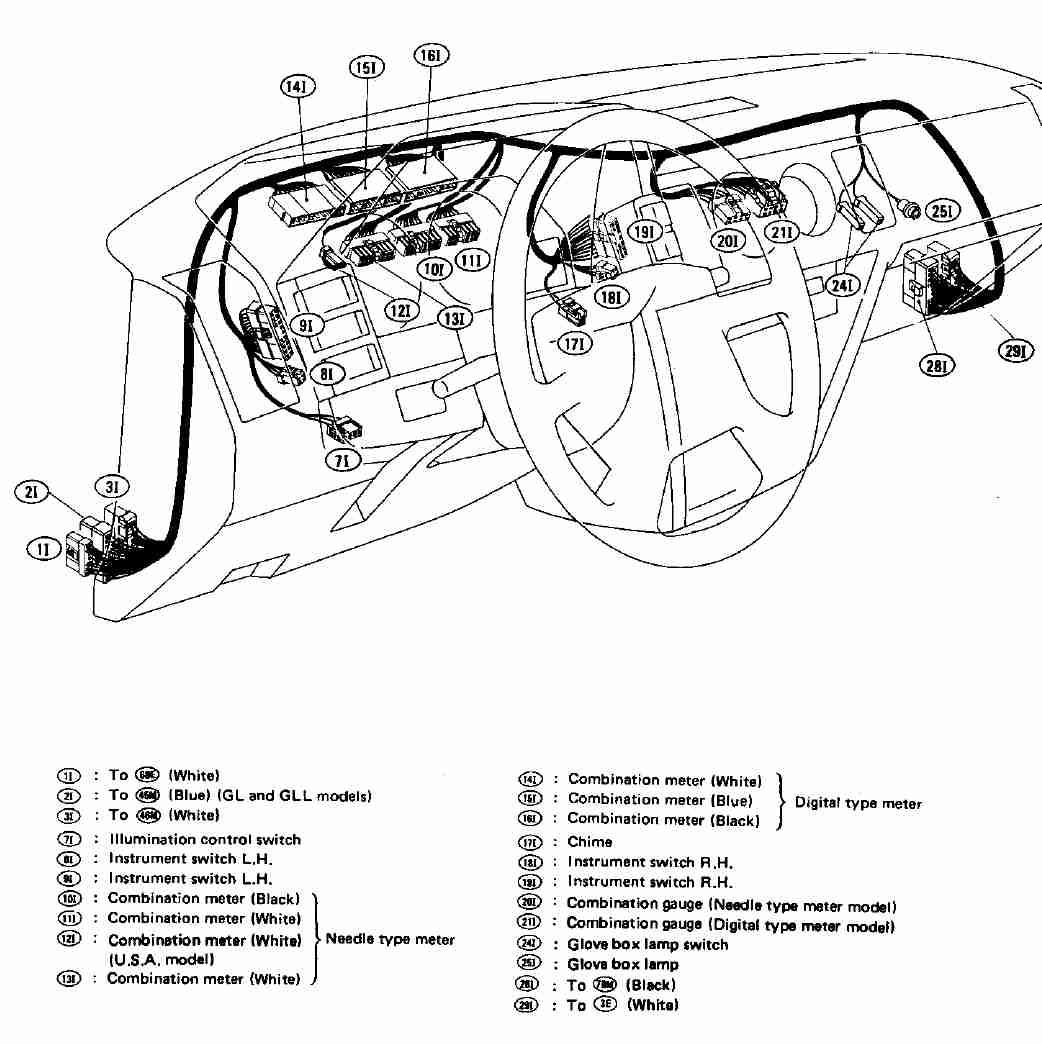
Anyway it matches the diagram. right to left: Red/Black Red/White White/Blue
I've been planning on digging that signal out and feeding it to Megasquirt so that I can log it.
If I can log speed sensor alongside tach, should be relatively trivial to calculate horsepower and torque; not valid numbers, but something that'll show increases and decreases better than the butt dyno does.
88ss, MegaSquirted.
t3/t4 60-1 cold, stage 3 hot, FMIC
450cc DSM injectors, walbro 255 http://www.z-toys.com/ Boost gauge and MS info
This is the Innovative calc provided with inputs RPM ACCEL SPEED :
I've adapted to z31 weight, Cd :
#mlb is mass in lb
mlb = 3410
#dia is tire diameter in inches
dia=25
#?Vehicle weight in kg = m
m = mlb * 0.4536
#?Tire diameter in cm = td
td = dia * 0.3937
#?i Name of RPM channel = dl32_1
rpm = dl32_1
#?i Name of Acceleration channel = dl32_5 {g}
ACCEL = dl32_5
#?i Name of speed channel = v {m/sec}
vmph = dl32_3
v = vmph * 1609.3 / 3600
#Frontal area of vehicle (sqm) = Ar[2]
Ar = 1.865
#Drag coefficient = Cd[0.45]
Cd = 0.380
# ?Current atmospheric pressure (millibar) = atmp[1013.2] # sea level 29.92"Hg
atmp = 1013.2
#?Current temperature (degC) = temp[15]
temp = 15
#SAE correction factor
SAEcf = (1.18 * ((990/atmp) * sqrt((temp + 273.15)/298)) )- 0.18
#air density
density = 0.0412236 * atmp/ (temp + 273.15)
R = td / 200 #tire radius in m
# aerodynamic draq in Newton
Fa = 0.5 * density * (v^2) * Ar * Cd
F = (m * ACCEL/9.81) + Fa
powr =v * F * SAEcf/745.7
MC(RWHP;hp;0) = powr
MC(RWtorque;Nm;0) = powr * 7121/rpm
This is one is based on just RPM and ACCEL:
#m is mass in lb (assuming 150lb Driver)
m = 3410
#dia is tire diameter
dia=25
r=dia/(2*12) # radius in feet
#final diff ratio
finaldrive=3.7
gear_ratio=1.000 # assume 3rd gear pull, no overdrive
F = m * dl32_5 # dl32_5 is accelerometer channel
trq = F * r / (gear_ratio * finaldrive)
MC(torque;lbft;0;500) = trq
MC(power;hp;0;500) = trq * dl32_1 / 5252
#dl32_1 is the RPM channel
It was the Red/white wire in the first photo I showed.
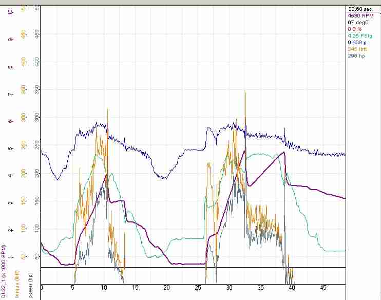
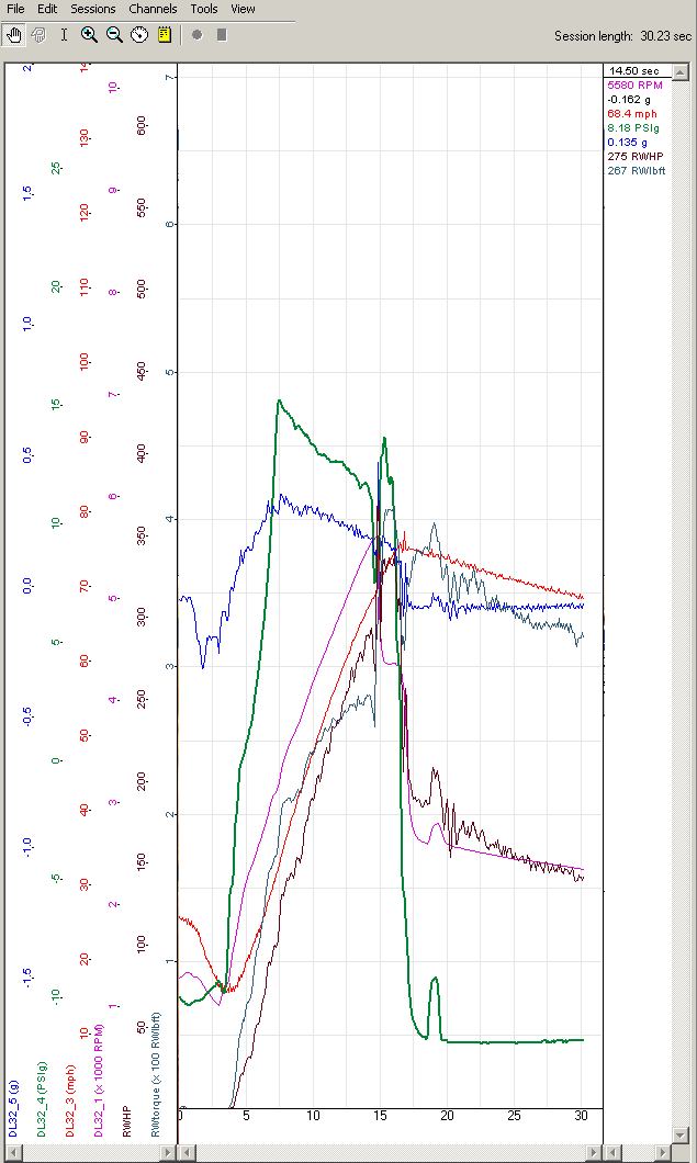
Need to calibrate the speed, but just for fun here is my first log with it:
Speed seems close but the HP/torque calculations don't look correct to me. I had to multiply the resulting RWHP and RWLBFT by 100 to get these results.
15 psi run rolling start up a freeway ramp. PSI drops off from 15 to 10.
This getting to be fun. Still need the WB O2 installed.
Hi!, I'm still around....
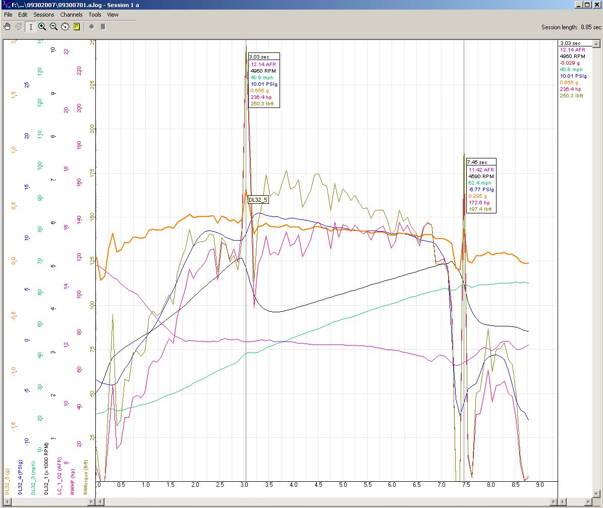
Anyway I got back into my car . I have the LC-1 WB O2 installed and working.
Want to log the Cyl Head temp sensor . Using all the dl32 channels now , need an SSI-4 I guess...
Speed sensor line worked fine, I've set it to a max speed of 140MPH@ 5volts. Anyone know how high the digital speedo will read? Probably runs over 5 volts ?
RPM is from Tach Output from MSD Digital 6 Plus, very smooth precise/accurate
Here are some links to my DL-32 configuration setup doc file and firsts logs....
 Tweet
Tweet

Comment