 Tweet
Tweet

There's the kit I bought for 13 dollars from rockauto.com when I bought my steering rack. It's more expensive here in Canada so I chose to purchase it and save on shipping as a double-packed order.
Gates #348870 Rebuild Kit Contents:
1 x Split Lock Washer for Pulley Nut
1 x Snap-Ring
1 x Oil Shaft Seal
1 x Main Housing Seal
1 x Large O-Ring Seal
1 x Medium O-Ring Seal
2 x Small O-Ring Seals
2 x Copper Gasket Washers
Here's a visual:

Additional Part Required (Choose One of the following):
- NTN Bearing #6202LB
- SKF Bearing #6202-RZ
- Any Other #6202 Bearing measuring:
---- Height: 11mm
---- Inside Diameter: 15mm
---- Outside Diameter: 35mm
To Dis- and Re-Assemble, you need:
- 10mm, 12mm, 14mm, 24mm Wrenches
- Snap-Ring Pliers
- ATF / PS Fluid / Assembly Lube
- Cotton Swabs and Shop Towels
- Green Scoth-Brite Sponge Pad
- Shop Press or a Friendly Machinist
- Acid Dip of Housing Recommended
It's fairly straight forward to take something apart, and when you do take it apart, you won't have to read this guide to put it back together. So I'm just going to post pictures with short captions to explain what's going on here.
Here goes...
You'll want to start by removing the pulley. You'll have to put the pump in a vice to get any of the bolts off of this thing. They're on there good.
Once you have that off, you can remove the Snap-Ring using a suitable tool (Snap-Ring pliers) Keep in mind, I had the new bearing installed in this picture, so we're just looking at the Snap-Ring here.

Now that the snap ring is out, you can see the entire sealed bearing. This #6202 series sealed bearing is not included in the kit:

The bearing shown previously is the SKF version of this bearing that was available to me. Slightly different in construction, but it does not come in contact with any oil or chemicals.
The seal below is the original Nissan one that was removed. The new gates one is supplied in the kit and is the same. Without removing the bearing, it's anybody's guess as to where it would go. I had my machinist press it out for me, and install the new bearing and the new seal. The Seal goes in FIRST, then the bearing pressed in after. This is why it doesn't matter what the constrution of the bearing is like, as long as it's relatively the same and the recommended use is virtually for the same type of load, which the SKF one is.

This guide will not show the seal as installed because I had it pressed in for me by my machinist. But you get the general idea. Just don't try and hammer it out. It won't fly out that easy. After replacing the bearing, the shaft is noticably tighter and it moves very smooth. It should not whine or make noise now.
Here is the Nissan sealed bearing for comparison. It is shown beside the copper gasket washers to show its relative size and NTN Part Number.
raxs.com/share-6F6A_4AF51913.html">

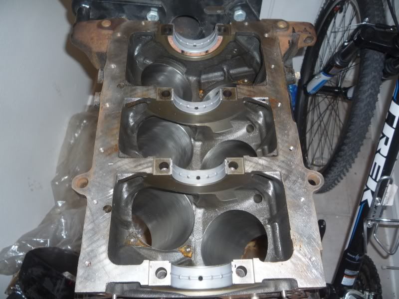
Turn the pump around to expose the inside. At this point, you should have removed everything from the inside. Actually, you should have done that before cleaning it. Before final assembly, you'll want to use a Green Scoth-Brite Sponge Pad to remove the rust from the case mating surfaces. It's usually only the outside of the gasket that gets rusted anyway, but just do it and be safe.
You will see there are no seals here.. Just the splined shaft that was pressed in with the bearing.

So the large and 1 of the small o-rings will go in now. Apply some of the recommended lube at the top of this guide, and make sure you're applying it to a clean pump housing. The lube will suspend dirt, and that's not a good thing for pumps. Install the seals like so:

You may be thinking... The small o-ring doesnt look like it goes there. It does. It is pushed down by a piece that goes in on the next step. It only feels weird because the old o-ring was compacted into shape and stuck on the housing. These o-rings just rest on the lower lip. They do not sit on any groove. They sit on a rounded step/ledge.
So now you take the lower pump plate and the spring that goes underneath it:


Give it a good cleaning and lubing, and first slide in the spring like so. You can lube the base of the spring to be extra cautious. I chose to do so. (This photo displays the o-rings quite well too incase it wasn't clear):

Then you can lube up the sides of the lower plate and slide it in next. Pay special attention to the notches in the sides for the location dowel pins that come in a later step. Just get them close, or use one of the dowels now to align it if you feel it's easier at this time. The piece is symmetrical from one half to the other, so you do not need to re-align the dowels to any specific orientation other than "lined up"

Lube up the upper impellar casing on the inside, and the outside. The outside does not move but lubing facilitates installation and removal or spinning to locate the dowels.

Notice the N is facing "up", away from the front of the pump (not actually up in the picture). This is how mine was taken apart. I also put the "N" back in the same spot, closest to the dowel it was removed from. You can look at the back of the pump case to see where yours was. You can also install the dowels there too now, if you like:

Here is what the impellar gear/drive looks like. It has small vanes/fins that get forced out through hydraulic pressure. They in turn, compress and force fluid through the small jet in the pump that acts as a restrictor to build up extreme pressure. This gear/drive was installed with the the "S" marking facing down against the lower plate. My theory is that the "N" may have been for "North" as in "up" when looking at it from the top down, as a person rebuilding it would be doing.

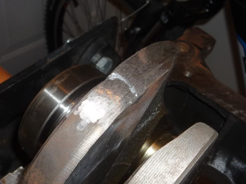
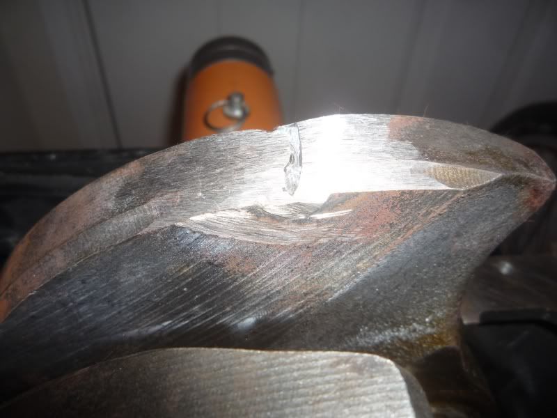
Below is a close up of the two edges you will find in the impellar vanes/fins, or whatever they're called. They are rounded on side. As stated per the FSM, and as seen during dis-assembly... The rounded side is the side that touches the casing. It's the outer tips of the "star" formation that they create, so to speak.

Here's how they install:

Here is what they look like all installed with the gasket layed over-top: Pay special attention to the teardrop in the bottom of the gasket that uncovers the hole that the fluid is pumped through. Basically the tear drop is on the same half of the threaded hex fitting, and the hole is on the same half of as the bracket mounting bolt hole.

There is one last seal inside the hex-fitting area where the pressure orifice is. I could not remove the hex-fitting, so I will have to give it another go tomorrow. In the following picture, you can remove the hex-fitting at the top with a 24mm (I think) wrench. It's on there tight and the second small o-ring will go between some spring contraption and it's seat (that's what the FSM says, I haven't opened it up yet).
The picture also shows where the medium size o-ring gasket goes. Right at the inlet- the hole with the bolt hole just above it (and below it, but not shown).

That's basically it. use the FSM for torque specs or just torque it till it's very very very tight because the original bolts took a long-bar to remove. I'm going to be holding the case together with the original bolts to spray it, then I'm going to be using new bolts to close it all up. Pretty easy to do if you have a couple of hours. Takes about 1 hour TOPS if you're cleaning everything and not replacing the main oil seal or the bearing, which you most likely don't have to do, but hell, I'm there.
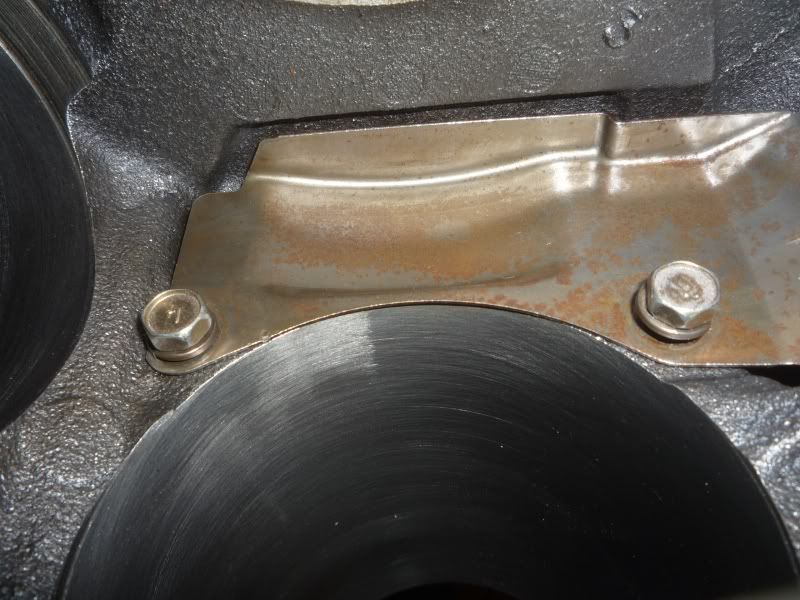
And if anyone is wondering about what mods were done to allow it to fit the VG33ET using the 87 Z31 bracket:

Measure + Grind. It's about 10 - 15 mm of grinding on the boss where the bolt goes through. You can then move it forward and you must space out the rear of the pump with a washer or a ground-down nut. Don't forget to make another one of those spacers for the tensioning bracket as well.
I'll answer any questions as they're posted.


Comment